


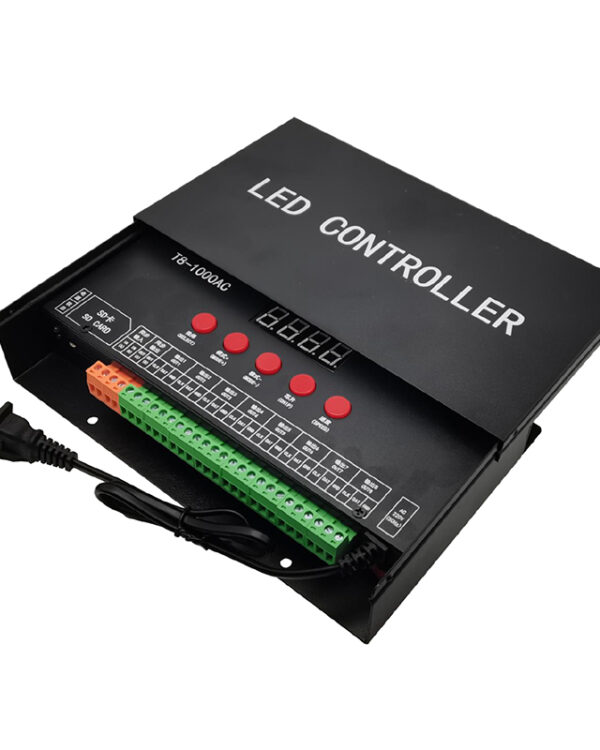
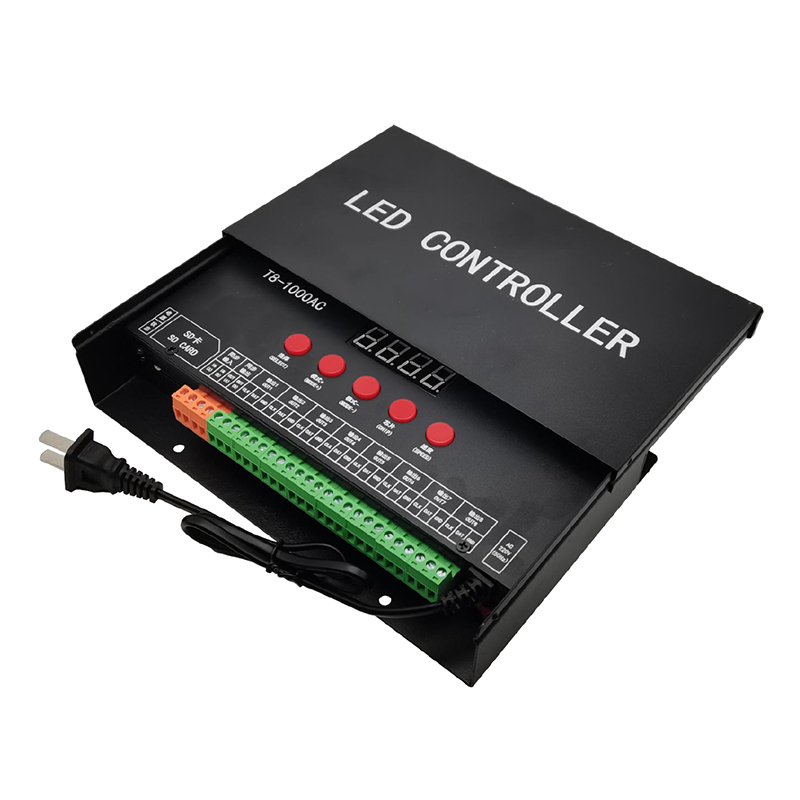
T8-1000AC LED Controller for Digital LED Strip Lights
I. Features of T8-1000AC System:
- 8-channel output, each channel carries 1024 points, and the maximum load of a single controller is 8192 points.
- Support high-voltage, cascade and two hybrid synchronization modes.
- Play built-in effects without SD card. There are 99 Kinds of built-in effects, and support full broadcast, unicast and anycast functions.
- When inserting the SD card, play the effect files in the SD card. The SD card can store up to 32 effect files. Each effect file can contain up to 100 programs, and the total number of programs does not exceed 100. The programs support full broadcast and unicast functions, and the SD card capacity supports 128mb-8gb.
- It can be equipped with our “gps-sync synchronization controller” for cluster synchronization.
- The LED digital tube is used to display the controller information, which is resistant to low temperature and is not affected by ambient temperature.
- The controller provides 5 entity keys for setting various parameters, which is simple and reliable.
- The design of pull-out rainproof shell is especially suitable for outdoor engineering construction.
- AC 220V power supply, with a 2-pin plug, makes the test and construction extremely convenient.
- Each controller is presented with a 2-inch slotted screwdriver, which completely solves the trouble of finding suitable tools during wiring.
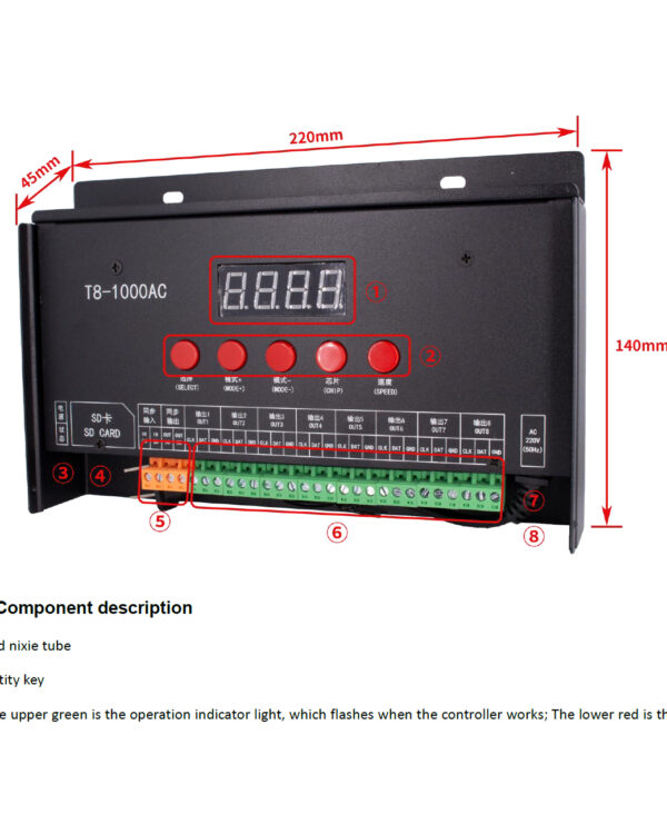
II. Product Structure:
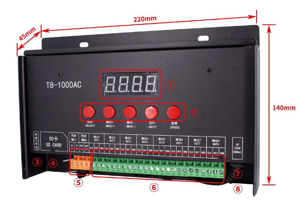
① Led display
② Function keys
③ The upper green is the operation indicator light, which flashes when the controller works; The lower red is the power indicator, which is constant after power on.
④ SD card slot
⑤ The left two bits are synchronous input ports; The two bits on the right are synchronous output ports.
⑥ 8-channel output port
⑦ AC 220V power cable, 50cm long, with a 2-pin plug.
⑧ Power switch
III. Product Parameters:
Working voltage:AC220V 50Hz
Rated power:<1W
Weight:1.1KG
Product size:220mm x 140mm x 45mm
Enclosure type:Pull type rainproof iron shell
Output port:8-way TTL output port (does not support DMX512 lamps)
Number of loaded lamps:1024 lamps / channel, 8 channels, 8192 lamps in total
SD card type:SDHC
SD card capacity:128MB-8GB
Effect file format:FAT32
Effect file type:*.LE
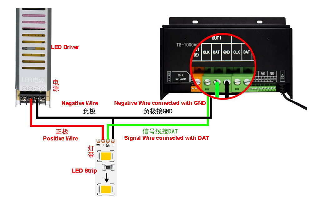
IV. Wiring Diagram:
The controller can be used by a single machine or multiple machines. When a single machine is used, it only needs to supply power to the controller and connect lamps.
The use of multiple machines means that two or more controllers work synchronously, and the controllers are required to work in step. T8-1000ac supports three synchronization modes: simple high-voltage synchronization, highly reliable cascade synchronization, and GPS / BD distributed synchronization. It also supports the mixed use of three synchronization modes. The installation and connection of the controller are different due to different synchronization modes, which are introduced below.
The controller comes with built-in effect. When the card is not inserted, the effect file in the SD card will be played automatically when the SD card is inserted and then turned on. When a single machine is used, you can freely choose which effect to play, but when multiple machines are used, all controllers involved in synchronization must choose the same, either all the built-in effects or all the SD card effects. When playing SD card effect, the effect file in SD card must be exported from the same project. Failure to do so will result in synchronization failure.
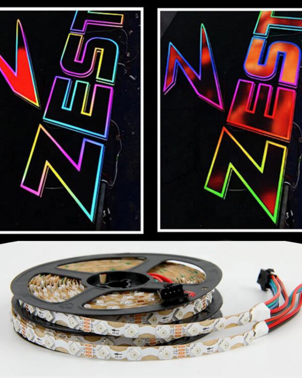
T8-1000ac supports lamps with various TTL signals such as through-hole lamps, point light sources, line lamps and lamp strips, but does not support DMX512 lamps. Whether to support specific lamps, please ask the lamp manufacturer for lamp parameters and ask our business personnel or agents.
A. Standalone Use:
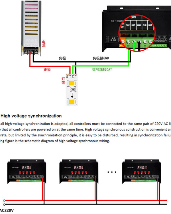
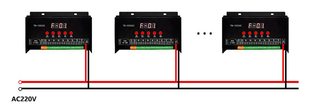
B. High voltage synchronization:
When all high-voltage synchronization is adopted, all controllers must be connected to the same pair of 220V AC lines, or ensure that all controllers are powered on at the same time. High voltage synchronous construction is convenient and easy to operate, but limited by the synchronization principle, it is easy to be disturbed, resulting in synchronization failure. The following figure is the schematic diagram of high voltage synchronous wiring.
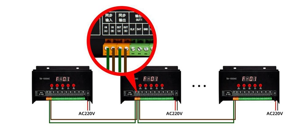
C. Cascade synchronization:
When cascade synchronization is adopted, the controller power supply does not need to be connected together or powered on at the same time, but the synchronization line needs to be connected.
It is recommended to use shielded pure copper twisted pair (such as network cable) for the synchronization line. The connection mode of the synchronization line is: connect the synchronization output port of the controller 1 to the synchronization input port of the controller 2, and the synchronization output port of the controller 2 to the synchronization output port of the controller 3, Connect to the synchronization input port of the last controller in turn, and a is connected to a and B is connected to B, as shown in the figure below.
After the synchronization line is correctly connected, the nixie tube of controller 1 displays p-0.0 (display f-0.0 when playing the built-in effect.), The decimal point is displayed after the number, indicating that it is the host. The nixie tube of all other controllers displays p-00 (f-00 is displayed when playing the built-in effect). The decimal point is not displayed after the number, indicating that it is the slave. If there is a decimal point displayed on two or more controllers, it indicates that the synchronization line is not connected correctly. At this time, it is necessary to check the synchronization line connected to the synchronization input port of the current controller.
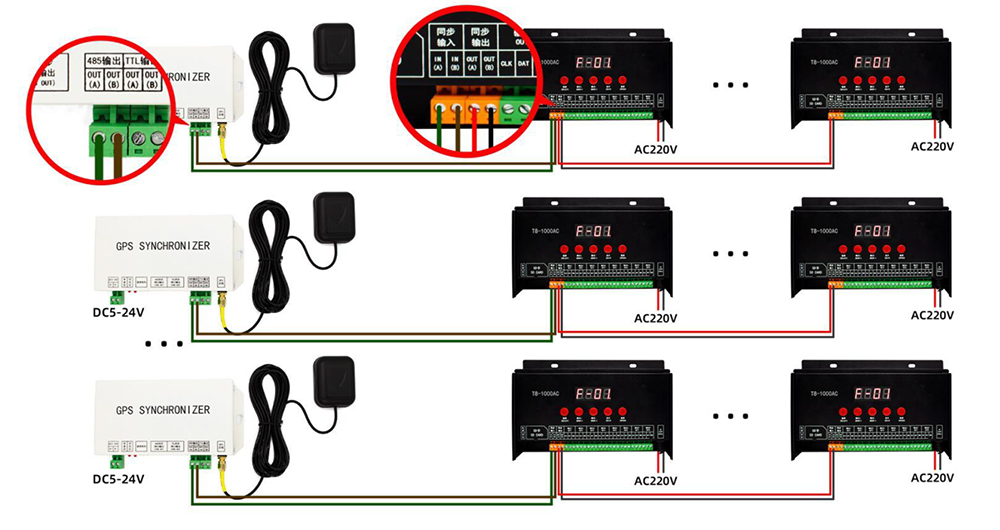
D. GPS / BD synchronization and cascade synchronization are mixed:
When GPS / BD synchronization is used, cascade synchronization must be adopted between controllers. After each GPS / BD synchronization controller, multiple controllers can be cascaded to form a synchronization unit.
Multiple synchronization units do not need any connection and are not limited by geographical distance, so large-scale synchronous playback can be realized. The wiring mode is shown in the figure below: